There
is a version of body movement - curvilinear - oscillatory process (for
example, at a physical pendulum) which is possible to organize so that
the projection of tangential pendulum acceleration to the allocated direction
would not change direction during all period of fluctuation. Such process
is realized in inertor.
In the latter, for transformation of rotary movement
of a body (debalance) in rectilinear movement, the gyroscope is applied.
We consider it necessary to remind the reader of free gyroscope properties.
- The gyroscope has inertia plane and it coincides with gyroscope own rotation plane.
- If we apply cross working moment Mп on inertia plane the gyroscope turns its vector on 90∞ in a course of own rotation.
- The gyroscope resists (counteracts) to cross turn of its inertia plane with the force proportional to moment Mп value (thus, the higher the turn speed of inertia plane, the greater the counteracting moment is).
- Acting Mп and
counteracting gyroscope moment
 are always numerically equal and opposite to each other.
 - Under action of constant cross moment Mп gyroscope inertia plane rotates with constant speed (around moment Mп vector revolved on 90∞). That means it and gyroscope turn without acceleration!
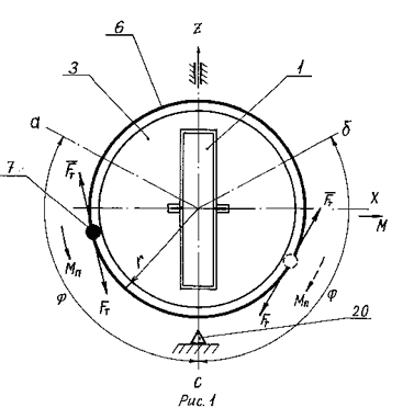
The
scheme, explaining the inertor action principle, is given on drawing I.
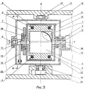
Inertor is shown in a transverse section. Drawing 3 and 4 give the mover
assembly variant. The device has a drive, which is the electric motor,
containing stator 3 and hollow rotor 6. Inside stator 3 the gyroscope
1 is installed. M is its vector of the kinetic moment. Debalance 7 is
fixed on a rotor 6. Mover is joined by an axis 19 to the vehicle body
16 with an opportunity of free rotation on it. Stator 3 and rotor 6 can
freely rotate both relative to each other, and jointly on the common axis
9. On the body 12 the gauge 20 intended for angular debalance position
control 7 is installed. Points a, b and с belong to a trajectory of rotation
of the centre of debalance mass 7 around axis Y. r-radius of rotation
of the centre of debalance mass 7.
In addition the drive structure includes the control
device for engine reverser and some more some auxiliary elements which
are not shown on drawing I.
 In
an operating conditions the inertor drive provides curvilinear - oscillatory
movement of debalance 7 around axis Y with angular amplitude
 ![]() .
Let us consider the process more in detail.
.
Let us consider the process more in detail.
In an initial state the centre of debalance mass
7 is located in a point a, the gyroscope 1 is untwisted up to necessary
value of kinetic moment
![]() , where J
is a moment of gyroscope inertia,
, where J
is a moment of gyroscope inertia, ![]() - is own circular frequency of gyroscope rotation. The drive switches
and powers the electric motor. Thus, under the influence of starting moment
Mп, rotor 6, and debalance 7 with it start to get accelerated. Simultaneously,
starting moment Mп under the third NewtonТs law is enclosed to stator
3 (in direction opposite to rotor 6), and with it - to a gyroscope 1.
The latter does not allow stator 3 to rotate around axis Y and only turns
all drive on axis 19 around axis Y. Debalance momentum 7 proceeds up to
a point c. After a signal of the gauge 20 the engine reverser and the
moment of drive Mп change their direction to opposite one. Under its influence
a rotor 6 and debalance 7 slow down the rotation speed to full stop in
a point a. Thus, the first period of fluctuation ends and the next one
identical to described above begins.
- is own circular frequency of gyroscope rotation. The drive switches
and powers the electric motor. Thus, under the influence of starting moment
Mп, rotor 6, and debalance 7 with it start to get accelerated. Simultaneously,
starting moment Mп under the third NewtonТs law is enclosed to stator
3 (in direction opposite to rotor 6), and with it - to a gyroscope 1.
The latter does not allow stator 3 to rotate around axis Y and only turns
all drive on axis 19 around axis Y. Debalance momentum 7 proceeds up to
a point c. After a signal of the gauge 20 the engine reverser and the
moment of drive Mп change their direction to opposite one. Under its influence
a rotor 6 and debalance 7 slow down the rotation speed to full stop in
a point a. Thus, the first period of fluctuation ends and the next one
identical to described above begins.

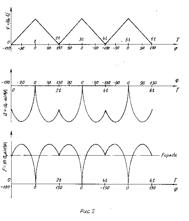
It is shown on drawing 2, how tangential speed V of
debalance m.c.(mass centre) change, a projection a to axis Z of tangential
m.c acceleration from a corner ![]() and time “ and force value of inertor traction F (a projection to an axis
Z of m.c. debalance tangential force of inertia
and time “ and force value of inertor traction F (a projection to an axis
Z of m.c. debalance tangential force of inertia ![]() m.c. debalance).
m.c. debalance).
Thus, debalance fluctuation period consists of four
subcycles of identical duration t, and in every odd subcycle (starting
from the first, initial one) its momentum occurs, and in every even subcycle
does braking. And during every subcycle, every period of fluctuation and
all operating time of a drive the projection of tangential force of inertia
![]() to an axis Z does not
change its direction (it always coincides with the direction of an axis
Z). It means that the whole drive together with the vehicle body will
move in space with acceleration towards an axis Z. We should bear in mind
that existence of forces of inertia itself speaks in favor of hypotheses
of gravitational expansion of the universe.
to an axis Z does not
change its direction (it always coincides with the direction of an axis
Z). It means that the whole drive together with the vehicle body will
move in space with acceleration towards an axis Z. We should bear in mind
that existence of forces of inertia itself speaks in favor of hypotheses
of gravitational expansion of the universe.
Let us consider the elementary one-dimensional case:
acceleration of a body under action of EarthТs gravitation field. We admit
that we are inside of a body and we are unaware of existence of globe.
If the body falls freely to the centre of the Earth we shall not find
out any a of speed cceleration. For us everything will occur so, as if
a body is in a condition of rest and weightlessness (there is an essential
distinction in that case when our body accelerates under the influence
of other body: we would find out at once the occurrence of unknown force,
which we would name weight).
Now let us imagine, that our body acceleration by gravitation
field is prevented by a motionless support: no matter whether it is terrestrial
surface or any other body. As the speed of a body changes, force of pressure
upon a support will appear, it is force of inertia of a body mass, which
we name a gravity or weight. If all Universe gravitationally extends,
i.e. each point of its space isotropically "swells", any change
of a body speed means counteraction to this "swelling". There
is a force which we name force of inertia. Therefore, it is possible to
draw a conclusion: what we name force of gravitation, is actually force
of inertia, i.e. forces of inertia and gravitation have common origin.
It is impossible to see mentally isotropy space
СswellingТ, neither to see mentally our Universe from outside. Sometimes
to show the way Universe extends more evidently, experts demonstrate the
simplified two-dimensional (one- surface) case: a surface of an inflated
ball, on which the points, simulating an arrangement of galaxies, are
put. We offer the reader to present mentally the same expansion, but in
all directions and on infinite set of surfaces simultaneously Е
Thus, it is possible to tell, that work on inertor moving
in space is carried out by the space itself or, to be more exact, - gravitation
of the Universe. It means namely that time and range of its flight in
space do not depend on value of an onboard stock of energy.
 Twisting moment is applied to debalance on the part of a drive.
![]() , (1)
, (1)
Where Fт Ц is the tangential force developed
by a drive, r Ц is rotation radius of debalance mass centre.
To simplify calculations we will suppose, that the moment
of ћп has constant value during all operating time of a drive, and the
own debalance mass is much more than rotor mass which we will not take
into account further.
Under tangential force Fт
influence debalance is accelerated, therefore tangential force of inertia
arises in opposite direction ![]() = Fт, which is actually inertor traction.
= Fт, which is actually inertor traction.
Projection Fт (and ![]() ,
accordingly) to axis Z does not change the direction during all the device
operating time, and its amplitude Fо changes (pulses) according to the
expression
,
accordingly) to axis Z does not change the direction during all the device
operating time, and its amplitude Fо changes (pulses) according to the
expression
Fо = Fт
· sin|![]() |, (2)
|, (2)
where ![]() Ц is an angle
counted from a switching point of a drive reverser (it coincides with
gauge 20 displacement at drawing 1).
Ц is an angle
counted from a switching point of a drive reverser (it coincides with
gauge 20 displacement at drawing 1).
Let's replace traction Fо , pulsing in time for a constant
in amplitude force F, numerically equal to the average subcycle value,-
F= Fт · < sin|![]() |
>, (3)
|
>, (3)
Where < sin|![]() | >
- is average value of a sine for
| >
- is average value of a sine for ![]() -
angle, F is traction.
-
angle, F is traction.
Let's copy the formula (3), thus:
F=m · aт< sin|![]() |>,
(4)
|>,
(4)
where т Ц is debalance mass, aT - tangential debalance acceleration (const).
Further, for convenience, we omit a module mark in formulas, but thus
we shall take always into account, that ![]() > 0, irrespective of a direction of readout of a corner from a point
of a reverser.
> 0, irrespective of a direction of readout of a corner from a point
of a reverser.
The capacity necessary for a drive debalance is equal to
![]() , (5)
, (5)
Where ![]() Ц is circular frequency
debalance rotation, V Ц is linear debalance speed, t
Ц is subcycle duration.
Ц is circular frequency
debalance rotation, V Ц is linear debalance speed, t
Ц is subcycle duration.
The length of a way, undergone by debalance mass centre during subcycle
is as follows:
 ,
(6)
,
(6)
Having substituted acceleration aT from (4) and time t from (6) in the
formula (5), we shall receive the following ratio for a drive capacity:
 ,
(7)
,
(7)
The formula (7) can be simplified, if one value of angular amplitude of
debalance fluctuation (i.e. angle ![]() is given) is only given. Average value of a sine is unequal for different
amplitudes and has a maximum for
is given) is only given. Average value of a sine is unequal for different
amplitudes and has a maximum for ![]() - angle
- angle ![]() 130∞:
130∞:
< sin 130 > ![]() 0,729856.
0,729856.
Let's substitute it into the formula (7) and we will transform it to the
following:
 ,
(8)
,
(8)
From (7) we receive traction value
 ,
(9)
,
(9)
For fluctuation angle ![]() = 130∞ the formula becomes simplier
= 130∞ the formula becomes simplier
 ,
(10)
Using (4) and (6) we find one subcycle duration of debalance fluctuation
 ,
(11)
For ![]() = 130∞ the formula
becomes simplier
= 130∞ the formula
becomes simplier
 ,
(12)
It is necessary to notice, that the ratio (12)
describes the period of fluctuation of a physical pendulum.
To estimate value of a mover fluctuation angle (in degrees) around axis
Z (for ![]() =130
∞) is possible from the ratio:
=130
∞) is possible from the ratio:
 ,
(13)
It follows from formulas (8) and (10), that the
less is debalance fluctuation radius r, the more the mass, the
more mover traction F and ,thus, the smaller drive capacity –
is required!
 We
should say that rather unexpected conclusion which our "common sense"
in any way does not want to agree with has turned out...
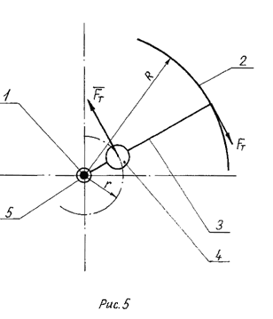
However, let us consider the following scheme
(see draw.5) where the debalance drive with hollow rotor is represented.
Its radius, for presentation, is considerably increased. The following
designations are introduced in it:
1 - an axis of rotation, 2 - hollow rotor, 3 - a bar, 4 - debalance, 5
- hinge, r - radius of debalance fluctuation 4, R -
rotor radius 2, Fт - the tangential force
developed by a drive, Fт - tangential force
of debalance inertia 4. The bar 3 connects a rotor 2 to the hinge 5. Debalance
4 is fixed on it too.
As
the moment of ћп of a drive is numerically equal to the counteracting
moment, created by force of inertia Fт
(for simplification, let us consider the own moment of inertia of a rotor
2 equal to zero), is possible to make up the following ratio:
ћп = Fт · R = ![]() · r
· r
This is known rule of the lever (see [28] p. 433), whence it is received
![]() .
That was to be proved.
.
That was to be proved.